Post Mixing Optimization and Solutions
Search:

PBT Mixing H

Mixing time simulation using CFD

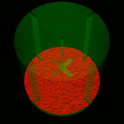
This CFD represents a mixing time experiment using a 45o pitched bladed turbine (PBT). The fluid to mix is spread out upon the base of the tank. Notice that the last zones of mixing are behind the baffles.

If you want to see the action again, click on your reload button of your web browser otherwise wait for it to reload automatically.

Computational Fluid Dynamics, or in this specific case, computational fluid mixing is a very powerful tool when experimentation is either not possible, dangerous, or too expensive.

Ask Post Mixing for a quote on CFD experiments for your process and reactor. We are not limited to mixing tanks. We can also do static mixers and mixing in pipes, etc. and even subjects like mixing honey in your tea.

Click here for more CFD and CFM examples.

If this is what you are looking for, fill out our Contact Us form. 
We will get back to you as soon as possible.

For those of you that have imaging 
					turned off, or a slow internet connection, this picture will show the 
					mixing of materials on the base of a tank and a PBT.

Description of this CFD

Basic Summary of the Physical Conditions:

  • Standard turbulent tank 0.24M Dia, 0.24M Deep, with 4 baffles and 45o pitched bladed turbine (PBT)
  • Impeller diameter D = 1/3 * Tank diameter T , and bottom clearance = 1/3 * Z
    Impeller speed, N = 250 RPM, counterclockwise rotation
  • Fluid is water, density (Rho) = 1000 kg/m3, viscosity (Mu) = .001 kg/ms
  • Species Dispersion:
    Initial Conditions - 6% by Volume at bottom of tank, Concentration = 1.0
    Final Conditions - dispersed 6% concentration throughout the volume
    Fluid characteristics - identical to water - viscosity and density
  • Procedure / Assumptions:
    Fluid Flow solution to steady state, then study transient dispersion
    This differs from the assumption of totally transient dispersion i.e.
    Fluid initial conditions at rest rather than initially at steady state flow.
  • Note for this case, steady flow is reached in approx. 5 seconds.
  • Computational Model:
    • 1.28M tetrahedra, using minimal definition Rotating Reference Frame
    • Turbulence Model = Spalart-Allmaras
    • Delta t for transient species = 1.0 sec
  • Computational Solution:
    • 1.8 Ghz Intel Laptop - 512MB memory
    • Flow Solution: 16 Non-linear Iterations to convergence (.001 tolerance)
    • CPU Time (elapsed): 2h, 12min
  • Transient Species:
    • 25 steps (.001 tolerance) - using up to 10 nonlinear steps per iteration to reach convergence
      CPU Time (elapsed): 2h, 6min
  • Results Animation:
    • Tracks the 5% Isosurface as a function of time.
    • Interpretation of which is that below and subsequently within the volume is concentration that is greater than 5%.
    • There are 26 animation frames consisting of initial condition and 1 second intervals for 25 seconds. 
  • Notes:
    • toward the end, concentrations in trailing corners of baffles and walls.
    • programs are available to describe transient volume associated with concentration levels i.e. relative variance .0023 normalized by volume at 25 seconds, or volume fraction at 6% concentration = 0.99, the bulk of remaining 1% within range of .057 to .062 .

Contact webmaster with questions or comments about this web site.
Copyright 2003 - 2013 Post Mixing Optimizations and Solutions, LLC
Last modified: February, 2013
Web Design by Sandy Gifford, Graphic Design, Web Development, and Illustration