SX Pumper Characterization
Dimensionless Numbers
Three dimensionless numbers is all that is needed to distinguish
SX pumpers. These are the power number, Np, the flow number, Nq,
and the head number, Nh.

|
(1) |
|
(2) |
|
(3) |
QAq+Org is the flow rate being pumped through the SX circuit and consists of both aqueous and organic phases. PPumper is the power that is distributed to the liquid and is somewhat less than the amount of power measured at the motor by the motor efficiency.rDisp is the average density of the aqueous-organic dispersion. H is the head developed by the pumper for a dispersion of r Disp. It is determined as the difference between the fluids highest and lowest elevations assuming that line losses are minimal. TS is the tip speed of the pumper. N and D are the pumper speed and diameter, respectively.
Power-Flow and Head-Flow Plots
Together, the three dimensionless numbers (from Equations 1-3) describe two characteristic plots, power-flow and head-flow. Each plot is a function of the flow generated by the pumper. Every pumper design has its own characteristic lines. The gap between the blades and the orifice plate, C, and the size of the orifice opening, DO, also affects them. These lines are determined by experimentation. The disadvantage of using standard dimensional head-flow and power-flow plots is because the data is arranged in curves and is valid for only one particular size pumper. The advantage of using dimensionless numbers for the basis of the plots is because the data forms straight lines and they are valid for all sizes of pumpers. It is also easier to extrapolate linear expressions.
For the purpose of explaining the technique of scale-up, the characteristic plots of the Lightnin R300 will be used, since the R300 has been extensively described in the literature [2-6].
The R300 is an impeller with an upper disk having 6 full-length straight blades the disk (see Figure 2). The blade height to impeller diameter ratio is hBlade/D=0.2. For the creation of Figures 3-4, a 6-inch (152 mm) R300 was used. The pumper to tank diameter ratio is D/T=0.5. It is similar to a Holmes & Narver impeller except that the blades
are higher.
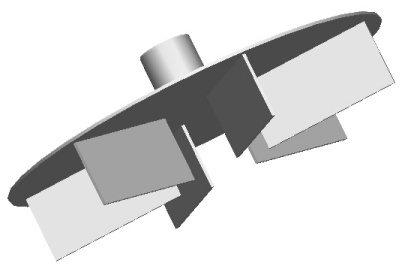 |
Figure 2: Lightnin R300 pumper
(3D drawing by P. Csiszar) |
The power-flow plot of the R300
shows the
uniqueness of pumper impellers. Whereas
the power number of open impellers is constant under turbulent conditions,
regardless of impeller speed, the power number of pumpers increases with flow.
Figure 3 shows several lines for the same pumper. The
difference in the lines is the size of the orifice relative to the pumper
diameter, DO/D. Within the scatter
of the data, there is no difference in the power number lines for DO/D < 0.5.
As DO/D increases beyond 50%, the power increases significantly at the
same flow rate. When DO/D=1, the
orifice is the same size as the pumper. At
DO/D=2, the orifice plate is gone and the pumper is just mixing the fluid.
Notice that the power number is constant.
In this situation there is no net flow through the SX-circuit, and Q has
been replaced with the flow being generated by the impeller blades.
The Dead-ended Point describes the lowest power consumption at no
net flow. This occurs when the
weirs between the stages have been shut.
 |
| Power-flow curves for the R300 pumper. |
The head-flow lines for the R300
are much different (see Figure 4). Most notably, there is a difference between the lines with
orifice ratios less than 50%. There is also a maximum head achievable for each orifice ratio, which describes the impeller line. This line is different for each pumper design and describes the upper head limitation of each design. Notice that the Dead-ended Point describes the maximum head
achievable by this pumper. The orifice lines describe the limitations of flow due to throttling by the orifice and other flow restrictions. Thus, for a given geometry, the composite head-flow curve of a pumper approaches asymptotically these two linear limitations.
 |
| Figure 4: Head-flow curves for the R300 pumper. |
For a given installation, the orifice ratio, DO/D is fixed. The standard orifice ratio of the Holmes & Narver pumper is DO/D=0.33. The head flow plot of
the R300
with DO/D=0.33 would look like this in Figure 5.
The meaning of the Frictionless Impeller Point can be found in the previous articles [3-5].
 |
| Figure 5: Head-flow curve of an R300 with an orifice ratio DO/D=0.33 |
Construction of the head-flow and power-flow plots
|